How many 8 awg in 3/4 emt – Navigating the intricacies of electrical wiring, we delve into a specific query: how many 8 AWG wires can be accommodated within a 3/4 EMT conduit? This exploration unveils crucial considerations for ensuring electrical safety and efficiency, empowering you with the knowledge to make informed decisions.
Delving into the interplay between wire gauge, current-carrying capacity, and conduit sizing, we unravel the factors that influence the number of 8 AWG wires that can safely reside within a 3/4 EMT conduit.
Electrical Capacity

Electrical capacity refers to the ability of a wire to carry electrical current without overheating or causing damage. It is primarily determined by two factors: wire gauge (AWG) and wire insulation.
Wire Gauge and Current-Carrying Capacity, How many 8 awg in 3/4 emt
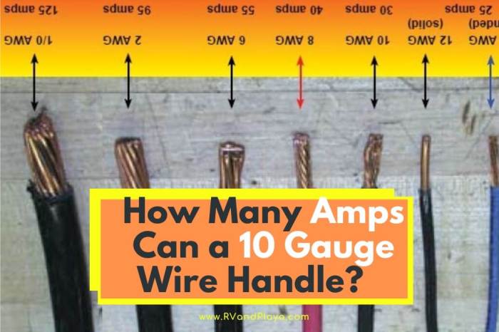
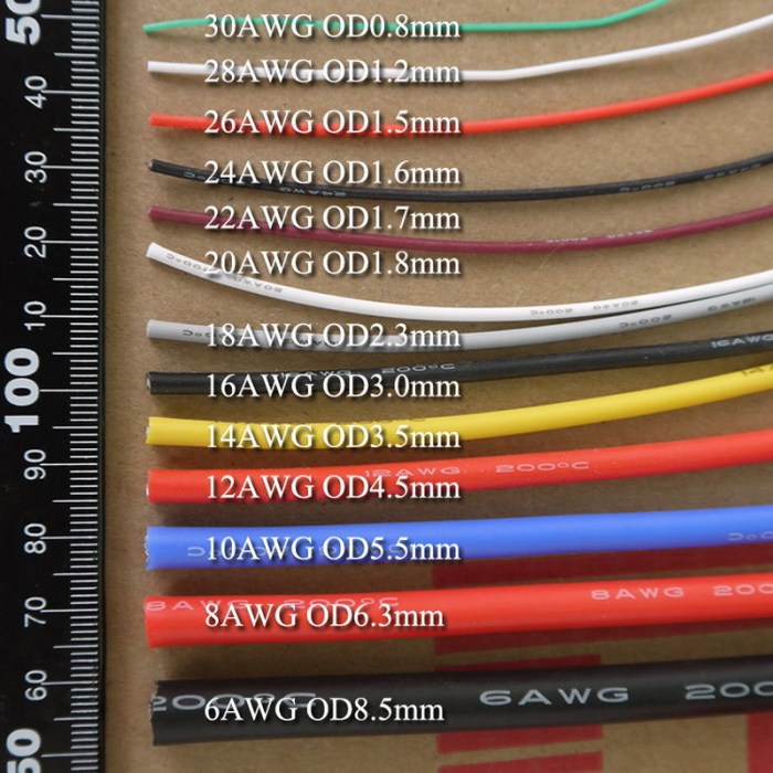
Wire gauge, measured in American Wire Gauge (AWG), indicates the thickness of the wire. The smaller the AWG number, the thicker the wire and the higher its current-carrying capacity. This is because thicker wires have a larger cross-sectional area, which allows for more electrons to flow through them.
Wire Insulation and Current-Carrying Capacity
Wire insulation also plays a role in current-carrying capacity. Insulation materials with higher temperature ratings allow wires to carry more current without overheating. This is because the insulation prevents heat from escaping the wire, which can lead to damage or even fire.
Conduit Sizing

Conduit Fill Ratio
The conduit fill ratio is a measure of how full a conduit is with wires or cables. It is calculated by dividing the cross-sectional area of the wires or cables by the cross-sectional area of the conduit.
The NEC requires that the conduit fill ratio does not exceed 40% for general wiring. This means that the cross-sectional area of the wires or cables must not exceed 40% of the cross-sectional area of the conduit.
Table of Conduit Fill Ratios
The following table compares the fill ratios of different conduit sizes for 8 AWG wire.
| Conduit Size (in) | Cross-sectional Area (in²) | Fill Ratio (8 AWG wire) |
|---|---|---|
| 1/2 | 0.82 | 32% |
| 3/4 | 1.27 | 24% |
| 1 | 1.81 | 18% |
| 1 1/4 | 2.41 | 14% |
| 1 1/2 | 3.07 | 11% |
Wire Bundling

Bundling multiple wires can significantly impact their current-carrying capacity. As wires are bundled together, the heat generated by each wire is trapped within the bundle, leading to an increase in temperature.
The NEC provides specific requirements for wire bundling to ensure safe and efficient electrical installations. These requirements include:
- The number of wires allowed in a bundle is limited based on the size of the conduit.
- Wires must be bundled in a neat and orderly manner.
- Conductors of different circuits must not be bundled together.
Current-Carrying Capacity of Bundled Wires
The current-carrying capacity of a bundle of wires can be calculated using the following formula:
Ibundle= I single
- (1
- (n
- 1)
- k)
Where:
- I bundleis the current-carrying capacity of the bundle (in amps)
- I singleis the current-carrying capacity of a single wire (in amps)
- n is the number of wires in the bundle
- k is a factor that accounts for the heat dissipation of the bundle (typically 0.5 for conduit installations)
For example, if we have a bundle of 8 AWG wires in a 3/4-inch EMT conduit, the current-carrying capacity of the bundle can be calculated as follows:
Ibundle= 30 amps
- (1
- (8
- 1)
- 0.5) = 24 amps
Therefore, the current-carrying capacity of the bundle of 8 AWG wires is 24 amps.
Voltage Drop: How Many 8 Awg In 3/4 Emt

Voltage drop is the reduction in voltage that occurs when current flows through a wire. It is caused by the resistance of the wire, which opposes the flow of current. The longer the wire, the greater the resistance, and the greater the voltage drop.
If you’re working on an electrical project that involves running 8 AWG wire through 3/4 EMT, you’ll need to know how many wires you can fit. The answer depends on the specific type of EMT you’re using, but as a general rule of thumb, you can fit about 4-6 wires in a single conduit.
For more information on this topic, check out this article on born worker by gary soto . It provides a detailed explanation of how to calculate the number of wires you can fit in a given conduit size.
Voltage drop is also affected by the wire gauge, with thicker wires having less resistance and lower voltage drop.
Calculating Voltage Drop
The formula for calculating voltage drop is:“`Voltage drop = Current (amps) x Resistance (ohms) x Length (feet)“`For example, if you have a 12-volt circuit with a current of 10 amps and a wire resistance of 0.01 ohms per foot, the voltage drop over a 100-foot length of wire would be:“`Voltage drop = 10 amps x 0.01 ohms/foot x 100 feet = 10 volts“`This means that the voltage at the end of the wire would be 12 volts
10 volts = 2 volts.
Voltage Drop and Wire Selection
Voltage drop is an important factor to consider when selecting wire for an electrical circuit. If the voltage drop is too high, it can cause the equipment at the end of the circuit to operate improperly or not at all.
In general, it is best to keep the voltage drop to less than 5%.The following table shows the voltage drop of different wire gauges for a given length and load:| Wire Gauge | Length (feet) | Load (amps) | Voltage Drop (volts) ||—|—|—|—|| 12 | 100 | 10 | 10 || 14 | 100 | 10 | 15 || 16 | 100 | 10 | 20 || 18 | 100 | 10 | 25 |As you can see, the voltage drop increases as the wire gauge decreases.
This is because thinner wires have more resistance.When selecting wire for an electrical circuit, it is important to consider the voltage drop and choose a wire gauge that will keep the voltage drop within acceptable limits.
Safety Considerations
Ensuring the safety of electrical installations is paramount. Improper wire sizing and installation can lead to hazardous situations, including electrical fires and shocks.
The National Electrical Code (NEC) Artikels specific requirements for grounding and bonding to minimize electrical hazards. These measures provide a path for fault currents to safely flow to the ground, reducing the risk of shocks and electrical fires.
Grounding
- Grounding connects the electrical system to the earth.
- It provides a low-resistance path for fault currents to flow, preventing them from traveling through unintended paths, such as through people or equipment.
- Grounding also helps stabilize voltage levels and reduce electrical noise.
Bonding
- Bonding connects different parts of the electrical system together, such as metal enclosures, conduit, and equipment.
- It ensures that all conductive surfaces are at the same electrical potential, reducing the risk of arcing and shocks.
- Bonding also helps improve the overall grounding system by providing multiple paths for fault currents to flow.
Safety Precautions
When working with electrical wiring, it is crucial to follow established safety precautions:
- Always turn off the power before starting any electrical work.
- Use appropriate personal protective equipment (PPE), such as gloves, safety glasses, and insulated tools.
- Inspect wires and equipment for damage before use.
- Follow NEC requirements for wire sizing, grounding, and bonding.
- Label wires and circuits clearly for easy identification.
- Get regular electrical inspections to ensure the safety of your electrical system.
FAQs
What is the maximum number of 8 AWG wires that can fit in a 3/4 EMT conduit?
According to NEC guidelines, a 3/4 EMT conduit can accommodate up to 12 AWG wires.
How does wire insulation affect current-carrying capacity?
Wire insulation plays a crucial role in determining current-carrying capacity. Thicker insulation provides better protection against heat dissipation, allowing for higher current flow.
What safety precautions should be followed when working with electrical wiring?
Always wear appropriate safety gear, including gloves and safety glasses. Ensure proper grounding and bonding to prevent electrical shocks and fires.